Product
Ingersoll Rand 99273906 Air Filter Element | M37 Compressor Intake
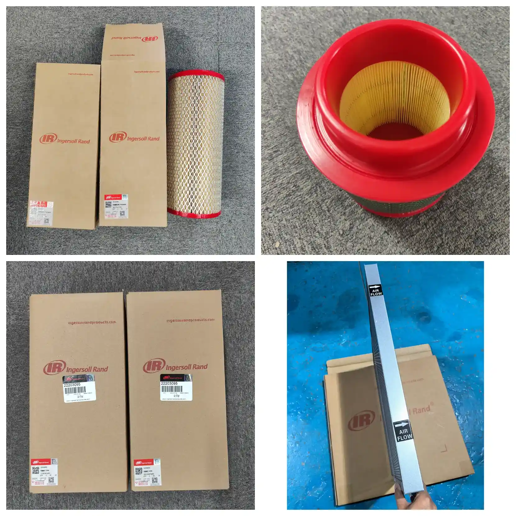
Genuine Ingersoll Rand 99273906 air filter element for M37 screw compressors. 270 mm OD x 120 mm H, 1.3 m2 media, 2-10 micron rating, ~2000 h service life. Export-ready, cross-reference support.
- Export packaging & documentation support
- OEM / ODM customization available
- Sample and bulk order workflow
Ingersoll Rand 99273906 Air Filter Element for M37 Screw Compressors
The 99273906 is the intake air filter element for the Ingersoll Rand M37 screw air compressor. It installs inside the air filter housing at the compressor inlet, upstream of the inlet valve, and serves as the first filtration barrier for the entire compressed air system.
As ambient air is drawn in, dust, grit, fibers, water mist and oil mist are captured by the media before reaching the airend - surface filtration intercepts larger particles while depth filtration retains finer ones. Only clean air is allowed into the rotor meshing zone.
The condition of this element directly affects airend service life. Hard particles entering the screw airend accelerate rotor and bearing wear, and simultaneously contaminate the downstream separator element, oil filter and lubricant, shortening all three. Severe blockage reduces intake volume, lowering discharge capacity and raising energy consumption; in extreme cases oil carryover can cause airend seizure. Replacing the air filter on schedule is therefore the lowest-cost protection for the airend.
Key Specifications
| Item | Value |
|---|---|
| Part number | 99273906 |
| Description | Air filter element |
| Application | Ingersoll Rand M37 screw air compressor |
| Unit discharge | 6 m3/min @ 0.7 MPa |
| Element outer diameter | 270 mm |
| Element height | 120 mm |
| Effective filtration area | Approx. 1.3 m2 |
| Filtration rating | 2-10 micron |
| Filtration efficiency | Greater than or equal to 98% for particles 5 micron and above |
| Initial pressure drop | Approx. 0.5-1.0 kPa |
| Alarm pressure drop | 6.0-6.5 kPa |
| Recommended replacement interval | Approx. 2000 hours (adjust to site conditions) |
Technical Data
Filtration Performance
| Parameter | Value / Notes |
|---|---|
| Filtration rating | 2-10 micron (industry range; some references state 2-10, 3-12, 5-10 or 10-15 micron) |
| Filtration efficiency | Greater than or equal to 98% for particles 5 micron and above |
| Filter class | HVAC filter classes (EN 779 G/M/F) do not apply; air filters are characterized per ISO 5011 by efficiency, intake resistance and dust holding capacity |
| Dust holding capacity | Approx. 380 g (estimated from 1.3 m2 effective area x 300 g/m2 typical for wood pulp media) |
| Beta ratio | Not applicable to air filters |
Note on beta ratio: Beta ratio is a hydraulic and lubricating oil filter metric determined per ISO 16889 multi-pass testing. Air filters are not characterized by beta ratio; they are evaluated per ISO 5011 using filtration efficiency, intake resistance and dust holding capacity. A beta value appearing in an air filter specification is usually copied in error from a hydraulic filter datasheet.
Flow and Resistance
| Parameter | Value / Notes |
|---|---|
| Rated air flow | Matched to M37 unit discharge of 6 m3/min @ 0.7 MPa |
| Filtration face velocity | Approx. 0.077 m/s (estimated: 6 m3/min / 1.3 m2, within the typical 0.05-0.15 m/s air filter range) |
| Initial pressure drop | Approx. 0.5-1.0 kPa (estimated) |
| Operating differential range | Approx. 1.0-6.0 kPa (estimated, from clean element to alarm point) |
| Alarm / final resistance | 6.0-6.5 kPa (estimated from unit differential pressure indicator setting; refer to the specific machine) |
| Pressure drop vs. energy | Each 1 kPa increase in intake resistance raises unit energy consumption by approximately 1% (estimated) |
Quantified relationship (estimated): Based on M37 discharge pressure of 0.7 MPa (gauge) and atmospheric pressure of 101.3 kPa, intake resistance raises the compression ratio:
| Intake resistance | Compression ratio | Relative energy increase |
|---|---|---|
| 0 kPa (new element) | 7.91 | Baseline |
| 2 kPa | 8.07 | +2.0% |
| 4 kPa | 8.24 | +4.1% |
| 6 kPa (near alarm) | 8.41 | +6.3% |
Engineering implication: As an element loads from new to alarm (0 to 6 kPa), unit energy consumption rises by approximately 6%. For a 37 kW unit running 6000 hours per year, this represents continuous excess power draw during the latter part of element life. The electricity cost of running a clogged element far exceeds the cost of a replacement element - the engineering basis for the factory-set differential pressure alarm.
Dimensions and Installation
| Parameter | Value / Notes |
|---|---|
| Dimensions | 270 mm OD x 120 mm H |
| Construction | Pleated (folded media wrap) |
| Effective filtration area | Approx. 1.3 m2 (estimated from 270 mm OD / 200 mm ID / 35 mm pleat depth / approx. 154 pleats; approx. 1.7 m2 if ID is 165 mm) |
| Pleat count | Approx. 150 |
| Pleat spacing | Approx. 4.8 mm (estimated: 738 mm mean circumference / 150 pleats) |
| Mounting interface | End cap located, matched to M37 air filter assembly |
| Sealing | Face seal (axial compression), estimated |
Procurement note: When cross-checking replacements, 270 mm OD and 120 mm H are the two most direct comparison dimensions. The ML37 / MU37 models in the same series use 39588777 (130 mm OD x 250 mm H) - the dimensional difference is substantial and the two are not interchangeable.
Materials of Construction
| Parameter | Value / Notes |
|---|---|
| Media | Imported wood pulp filter paper (industry-common US HV or Korean Ahlstrom media) |
| Media basis weight | Approx. 130 g/m2 (estimated, mid-range of typical 100-150 g/m2) |
| Inner / outer support | Galvanized steel perforated cage, approx. 0.6 mm thickness, open area 45% or above (estimated) |
| End caps | Metal end caps (galvanized steel) with polyurethane adhesive (estimated) |
| Seal | NBR seal ring (estimated; oil and temperature resistant, -30 to +100 deg C) |
| Bonding | Polyurethane (PU) hot melt adhesive (estimated) |
Operating Conditions
| Parameter | Value / Notes |
|---|---|
| Operating temperature | -10 to +100 deg C |
| Relative humidity | 80% RH or below, no condensation (estimated; wood pulp media loses strength and efficiency when damp) |
| Burst strength | Approx. 200-400 kPa per ISO 2758 (estimated) |
| Collapse pressure | Design differential pressure 10 kPa or above (estimated, approx. 50% safety margin over the 6.5 kPa alarm) |
| Special features | No flame-retardant, anti-static or moisture-proof ratings noted for this model |
Service Life and Maintenance
| Parameter | Value / Notes |
|---|---|
| Service life | Approx. 2000 hours (industry value, multi-source consistent) |
| Practical replacement interval | Reduce to under 1000 hours in dusty, sandy or humid environments; follow the differential pressure alarm |
| Storage shelf life | Approx. 2-3 years unopened, dry and ventilated conditions (estimated) |
Applicable Standards
| Item | Details |
|---|---|
| Product standard | ISO 5011 (intake air filters for internal combustion engines and compressors - performance testing), evaluating efficiency, intake resistance and dust holding capacity |
| Commonly cited test standards | ISO 2941 / 2942 / 2943 / 3723 / 3724 / 3968 |
| Standard applicability note | The ISO 29xx / 37xx series are general test methods for hydraulic filter elements (collapse/burst, structural integrity, material compatibility, axial load, flow fatigue, pressure drop vs. flow). Where a supplier can only provide hydraulic filter standards, request ISO 5011 or the OEM specification sheet. |
Standard Installation and Maintenance Steps
Single-person operation, approximately 20-30 minutes.
- Shut down, isolate power and release pressure. Press the emergency stop or stop button, disconnect the main power and apply lockout/tagout. Open the receiver tank drain valve to release system pressure and wait for the separator tank gauge to read zero. Criterion: gauge reads 0 and no residual air flow is audible.
- Locate and open the air filter housing. The M37 filter assembly is at the intake end of the unit. Loosen the housing clamp or end cap bolts and remove the cap. Criterion: cap not deformed, clamp not seized; treat a seized clamp before proceeding.
- Remove the old element and inspect its condition. Pull the old element straight out and examine dust distribution and media condition. Criterion: replace immediately if the media is torn, punctured, the end cap is debonded or the seal face is flattened, even if the interval has not been reached. Black oily sludge on the outer surface indicates abnormal oil mist in the intake - check the upstream environment.
- Thoroughly clean the housing interior. Wipe the inner wall and base with a lint-free cloth. Do not blow compressed air directly into the housing - this drives dust into the intake passage. Criterion: no loose dust on the inner wall, seal face flat and free of debris.
- Verify the new element. Compare old and new: 270 mm OD, 120 mm H, intact face seal with no gaps, undamaged media. Criterion: all three dimensions and the visual check must match; if any item does not match, do not install - re-verify the part number.
- Install the new element and refit the cap. Place the new element vertically into the housing, confirm it is fully seated at the base and the seal face is in contact with no trapped material. Refit the cap and tighten the clamp or bolts evenly in a diagonal sequence. Criterion: even gap between cap and housing, no visible skew.
- Start-up check. Restore power and run the unit for 5-10 minutes. Criterion: no abnormal whistling or intake noise at the inlet (unusual noise usually means the seal is not compressed or the element is not seated); air filter differential pressure indicator in the green zone.
The single rule of installation: Never start the unit before the element is seated. Running without an element or with an uncompressed seal allows unfiltered air directly into the airend, causing irreversible wear in a short time.
Frequently Asked Questions
Are 99273906 and 39588777 interchangeable?
No. 39588777 is for ML37 / MU37 models with a 130 mm OD x 250 mm H element; 99273906 is for M37 with a 270 mm OD x 120 mm H element. The dimensions differ by more than double and the two cannot physically fit the same housing. Verify by both model and part number when ordering.
How often should it be replaced?
Approximately 2000 hours under standard conditions. This is not a hard limit: reduce to under 1000 hours in high-dust environments (cement, foundry, woodworking, mining); extend appropriately in clean environments with short running hours. The most reliable method is to follow the air filter differential pressure indicator and replace at the alarm point.
What happens if it is not replaced?
Failure is a chain reaction with a clear economic cost. As the element loads, intake resistance rises; based on compression ratio estimates, energy consumption increases by approximately 6.3% as resistance goes from 0 to 6 kPa. If the media tears or the seal fails, unfiltered air enters the airend and dust contaminates the screw rotors, bearings, separator element, oil filter and lubricant simultaneously - repair cost escalates from the price of one element to the level of an airend overhaul.
How do I know it needs replacement?
Three signals: the differential pressure indicator enters the alarm zone (approx. 6.0-6.5 kPa); visual inspection after shutdown shows the media surface fully covered with dust and no visible pleats; discharge capacity drops while current or energy consumption rises. Replace on any one signal.
Can the element be cleaned and reused?
Not recommended. This pleated paper element is designed as a single-use part. Back-blowing with compressed air only removes surface dust; fine particles trapped in the depth of the media cannot be removed, and back-blow pressure can easily fracture fibers or deform pleat spacing, creating invisible channels that let unfiltered air pass. A cleaned element is visually clean but functionally failed - the risk outweighs the benefit.
What else should be checked when replacing the air filter?
Also check: whether the differential pressure indicator still responds (returns normally after reset), the intake hose for cracks or looseness, the housing seal ring for aging, and the inlet valve for correct operation. These parts work with the air filter; replacing only the element without checking the surrounding parts can quickly lead to intake problems again.
Is this a genuine part?
The 99273906 described on this page is an Ingersoll Rand OEM part number. Verify by the part number itself - the number is the only unambiguous identifier. Do not order based solely on 'fits M37' or visual similarity.
Do M37 and other M-series models use the same air filter?
No. Air filter specifications differ across the Ingersoll Rand M series: M22 uses 39588470 (130 mm OD), M37 uses 99273906 (270 mm OD), M55 uses 39708466 (278 mm OD), ML37 uses 39588777. Same series does not mean the same element - verify model by model.
What is the most common installation error?
Two: trapping material on the seal face or compressing the cap before the element is fully seated, causing leakage; and tightening cap bolts in a single-side sequence, causing uneven loading and skew. The correct method is to confirm seating, then tighten evenly in a diagonal cross pattern in stages.
Are there storage requirements for new elements?
Yes. Damp media swells and deforms, reducing filtration efficiency, and the metal cage corrodes when damp. Store on indoor shelving in a dry, ventilated area, off the floor and away from walls, water sources and oil contamination. Use unopened stock within 2-3 years on a first-in, first-out basis; long-term stockpiling is not recommended.
Compatible Machine Models
| No. | Model | Unit discharge | Air filter part no. | Element OD x H |
|---|---|---|---|---|
| 1 | M37 | 6 m3/min @ 0.7 MPa | 99273906 | 270 mm x 120 mm |
| 2 | M22 | 3 m3/min @ 0.7 MPa | 39588470 | 130 mm x 151 mm |
| 3 | M55 | 10 m3/min @ 0.7 MPa | 39708466 | 278 mm x 125 mm |
| 4 | ML37 / MU37 | 6 m3/min @ 0.7 MPa | 39588777 | 130 mm x 250 mm |
| 5 | 30S | 3 m3/min @ 0.7 MPa | 42855429 | 130 mm x 123 mm |
| 6 | 50S | 6 m3/min @ 0.7 MPa | 42855411 | 216 mm x 318 mm |
| 7 | 75S | 10 m3/min @ 0.7 MPa | 42855403 | 278 mm x 251 mm |
How to read this table
- The product on this page, 99273906, corresponds to row 1, M37; the other rows are for cross-reference within the series to help avoid mis-purchase.
- Row 4, ML37 / MU37, and row 1, M37, both have 6 m3/min discharge, but the air filter part numbers and dimensions are completely different - same discharge volume does not mean a common element, which is the most easily confused point in this series.
- If your unit nameplate model is not listed, provide a photo of the nameplate and the full model number; we will confirm by reverse lookup of the part number before ordering.
Note on machine generations
Ingersoll Rand M37 units exist in different production generations. The 99273906 described here is the intake filter element for early M37 models. Newer M37-75 series units (covered by the SL/SM37-75KW operation parts manual) use a different part number system in their parts manuals. If your unit is a recent build, verify against the parts manual supplied with the machine, or contact us to confirm by unit serial number. In practice, the most reliable confirmation is to read the part number from the old element itself.
Related Components
The M37 intake and lubrication system has seven components maintained on the same cycle as the air filter. They are listed below by location, function and inspection point; for specific part numbers, refer to the unit parts manual.
| Component | Location | Function | Inspection point |
|---|---|---|---|
| Oil filter element | Main oil circuit, between cooler and airend | Removes wear debris and sludge from lubricant, protecting bearings and rotors | Replace with the air filter; check housing seal face for oil seepage after replacement |
| Separator element | Inside the separator tank | Separates oil mist from compressed air and returns oil, controlling oil carryover | Check the oil return line for blockage during replacement (poor return directly causes excessive oil carryover) |
| Air filter differential pressure indicator | On the air filter assembly | Indicates element blockage and signals replacement timing | Should return normally after reset; a reading that never moves indicates failure and requires replacement |
| Coolant filter element | Coolant circuit, between cooler and filter | Keeps coolant clean, preventing scale and wear debris deposits | Replace together with the oil filter |
| Thermostatic control valve element | Between cooler and filter | Controls coolant flow through the cooler, maintaining airend operating temperature | If the unit runs cold continuously or gives high-temperature alarms, check the thermostatic valve first |
| Breather filter | On the separator tank | Balances tank pressure and prevents external dust from entering the oil circuit | Inspect on the same cycle as the air filter; shorten the interval in dusty environments |
| Intake hose and housing seal ring | Between air filter assembly and airend | Ensures no leakage or unfiltered air bypass in the intake path | Check for cracks, aging and loose clamps - bypass leakage is as harmful as running without an element |
Recommended group replacement: In high-dust sites, replace the air filter, oil filter and separator element together to avoid staggered maintenance intervals and repeated downtime. Schedule the coolant filter and thermostatic valve element on their own cycles.